Architecture of tnc@fhh 0.4.x
This article describes the architecture of tnc@fhh 0.4.x.
Therefore, the components which are used are listed and described, as well as the sequence of an EAP-TNC-authentication.
For a more basic overview of TNC, see Trusted Computing and Trusted Network Connect in a Nutshell.
For concrete contents of the mentioned configuration files and/or for detailed installation instructions, see the HowTos in the wiki.
Overview
tnc@fhh in its actual version (TNCUtil v0.4.4, NAA-TNCS v0.4.4, FreeRADIUS EAP-TNC-patch v0.4.5) consists of several components.
There are modules for external programs, dynamic libraries and configuration files, which the most of are in relation to some other components.
Components
- TNCUtil (libTNCUtil.a, header-files in /usr/local/include/TNCUtil/):
TNCUtil delivers some utility functions that are use by other components.
Furthermore, it includes a framework for developing IMC/IMV pairs.
- NAA-TNCS (libNAA-TNCS.so, header-file naatncs.h in /usr/local/include/):
NAA-TNCS is the implementation of both the NAA and TNC-Server component as proposed by the TNC architecture.
It is implemented as shared object that is plugged into a FreeRADIUS server.
- EAP-TNC-module: This plug-in mechanism is realised by extending FreeRADIUS with a new EAP-module called EAP-TNC.
This module is responsible for exchanging EAP-TNC packets between FreeRADIUS and NAA-TNCS.
- IMVs & IMCs (libIMV/IMC[…].so):
IMVs are the validating components who communicate with the IMCs on the clientside, and return a recommendation regarding to a IMV/IMC-pair-specific policy.
- FreeRADIUS: FreeRADIUS is a open-source Radius-server, which has EAP-functionality.
- wpa_supplicant: Currently, wpa_supplicant is used as NAR and TNCC cause it natively supports TNC and does not need any modification.
Configuration files
Additionally there are several configuration files for all of the components.
- /etc/tnc_config: defines the location of the shared objects of the installed IMVs.
- /etc/tnc/imv_[…].policy: the policy-file for a specific IMV
- /usr/local/etc/raddb/eap.conf: holds the configuration of the EAP-module, which includes EAP-TTLS and EAP-TNC.
- /usr/local/etc/raddb/dictionary.tnc: defines a new attribute TNC-Status, and three values (Access, Isolate, None)
- /usr/local/etc/raddb/dictionary: includes the TNC dictionary file
- /usr/local/etc/raddb/sites-enabled/default: configuration that is used after an successful authentication for mapping an TNC-Status (Access, Isolate, None) to a VLAN-ID
Operational sequence
1. Initiation of the modules
On the startup of FreeRADIUS, the EAP-module and the corresponding configuration file are loaded.
In the course of loading the EAP-module, the EAP-TTLS and the EAP-TNC-modules are also loaded.
The default-type for EAP is EAP-TTLS, as EAP-TNC has to be run inside of a secure tunnel.
Therefore, EAP-TTLS is configured to use EAP-TNC as its inner method, and it is also configured to send the reply-attributes from the inner method to the NAS, as EAP-TNC holds the result of the authentication.
2. Initiation of the TNC-authentication
When the first EAP_IDENTITY_RESPONSE (with EAP-TNC as the EAP-type) was received by FreeRADIUS, the method tnc_initiate from the EAP-TNC-module is called, which initiates the EAP-TNC-session.
In the beginning it checks if the packet is inside TTLS.
Afterwards an connection ID is calculated and the connection is created.
This is done by a method of NAA-TNCS, which is located in an shared object and provided via a header-file.
The method first loads all installed IMVs which are listed in /etc/tnc_config and informs them that a new handshake has begun.
tnc_initiate then builds the EAP-TNC-packet by setting all attributes in the request-structure of FreeRADIUS and settings the current stage to AUTHENTICATE.
Finally, the first EAP_TNC_RESPONSE is send to the peer.
3. Ongoing TNC-authentication
When a EAP_TNC_RESPONSE (and the current stage is AUTHENTICATE) is received, the tnc_authenticate-method within the EAP-TNC-module is called.
It basically forwards the EAP-TNC-data to the NAA-TNCS and forms an appropriate EAP_RESPONSE.
Again, the NAA-TNCS-shared object is used to send the EAP-TNC-message to the TNC-Server where all the messages from the EAP-TNC packet are extracted (from TNCCS-Batch to TNCCS-messages and IMC/IMV-messages).
The IMC/IMV messages are forwarded to the respective IMVs, which in turn can send a response or provide a recommendation to the TNCS.
Regarding to the resulting connection state, the handshake is either still ongoing (when one or more IMCs/IMVs have to exchange more messages) or the handshake is finished.
In the last case, the internal FreeRADIUS server-side-attribute TNC-Status is set.
TNC-Status is defined in the dictionary-file dictionary.eaptnc and has the values “Access”, “Isolate” or “None”.
Finally, an EAP-Response-Package is send back to the client/AR.
4. After an successful TNC-authentication
When the authentication was successful, FreeRADIUS uses the entries in the post-authentication-section of the default-policy.
By using the unlang-language, the value of TNC-Status is read and VLAN-settings (Tunnel-Type, ID) are added to the reply, which is then send from FreeRADIUS to the PEP.
Diagram of the components and their relations.
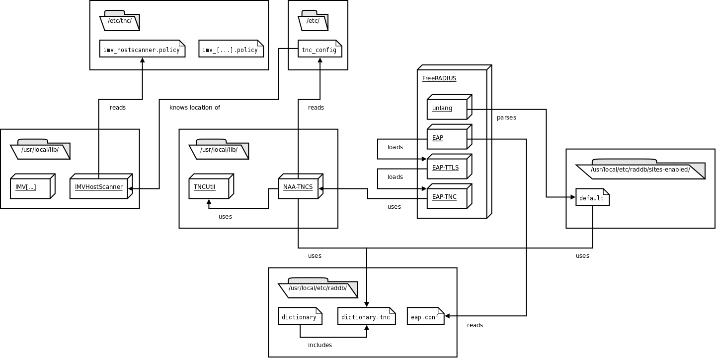 This picture shows all components that are used on the serverside of tnc@fhh.
16 Feb 2009
Trusted Computing and Trusted Network Connect in a Nutshell
This article aims to give a high level introduction to the basic concepts of Trusted Computing (TC) and Trusted Network Connect (TNC).
For detailed information please refer to the specifications.
Modern Threats to IT Security
The threats to modern IT-systems, especially networks, have changed significantly in the last years.
What used to be quiet static and homogeneous in the past becomes more and more dynamic and heterogeneous nowadays.
One reason for the more dynamic structure of modern networks is the growing number of mobile endpoints (PDAs, Laptops), that are dynamically connected to various networks accessing the services they need.
Correctly working IT-systems are necessary for a wide range of modern business processes.
As a consequence, they are an attractive target for attacks.
Therefore, IT-systems need to be adequately protected.
The latest news of the growing number of vulnerabilities, malware and (successful) attacks on IT-systems make clear that there is a need for new, innovative concepts to increase their security level.
Trusted Computing and the Trusted Computing Group
The TCG is a not-for-profit organization consisting of more than 170 members (ranging from hardware and software vendors to academic institutions).
The TCG develops an open, vendor-neutral framework that aims to significantly increase the security level of todays IT-systems.
The framework is described by a set of specifications which are developed by separate work groups within the TCG.
The overall goal is to increase the security level of modern IT-Systems by using so called “trustworthy” hardware and software components.
The crucial tool to achieve the stated goal is a passive hardware chip: the Trusted Platform Module (TPM).
The key concepts of Trusted Computing are summarized in the following sections.
What is Trust?
The term “trust” has a special meaning in the area of Trusted Computing.
TCG defines it as follows: “Trust is the expectation that a device will behave in a particular manner for a specific purpose.”.
That is, the term trust does not directly imply a “good” or “desired” behavior.
Instead, trust means that if one knows the current state of a device (e.g. a platform consisting of hardware and software), one can be sure how this device will behave (“good” or “bad”).
The problem here is that one must be able to securely obtain the current status of such a platform.
A platform that is able to securely report its own state is referred to as “Trusted Platform”.
TCG defines three fundamental features that each Trusted Platform must provide:
- Protected Capabilities
- Attestation
- Integrity Measurement, Logging and Reporting
Protected Capabilities refers to a set of “special” commands. Special means that those commands have exclusive permissions to access so called Shielded Locations. Shielded Locations are areas in memory where it is safe to operate on sensitive data. Ordinary commands are not able to access those Shielded Locations.
Attestation is the process of vouching for the accuracy of arbitrary information. This is for example the case when a platform wants to prove that is has a certain state (including used hardware, active software) to a second party (the so called verifier). Thus, the platform must be able to provide two kinds of information to the verifier:
- a measurement of its current state and
- a proof, vouching that the measurement is correct and really reflects the current state of the platform.
The reasoning whether the prove is sufficient and whether the reported state is “good” or “bad” is up to the verifier.
Integrity Measurement refers to the process of measuring the current state (the integrity) of a platform and storing digests of the taken measurements to Shielded Locations. Integrity Reporting is the process of reporting those taken measurements to a second party (formally: attesting to the taken integrity measurements). Integrity Logging is an (optional) intermediate step. It is about storing the taken measurements + further metadata to a log (the Stored Measurement Log) which does not reside in a Shielded Location. Logs can potentially ease further operations. But one must consider that logs can be easily compromised hence they are not stored in Shielded Locations.
The TPM is normally implemented as a passive hardware chip. Passive means that the TPM itself cannot actively influence the program flow of the CPU. It just receives commands and data from the CPU, fulfills the requested command, and returns a result.
Hardware TPMs are to some extend similar to smartcards (both provide a set of cryptographic features etc), with one major difference: each TPM is bound to a certain platform (e.g. soldered to a motherboard), whereas smartcards are normally bound to a user (and thus can be used across several platforms). Among other things, the TPM provides volatile and non volatile memory, a true random number generator, a SHA-1 engine and a RSA engine.
A TPM enables a platform to provide the fundamental features of Trusted Platforms stated above, including:
- Secure integrity measurements and reports: Integrity measurements can be obtained and the results can be securely stored “inside” the TPM. Based on those measurements, a TPM can be used to obtain a verifiable report that reflects the integrity state of a platform
- Sealing: Data can be stored in such a way that it is only accessible if a) the user authenticates itself successfully and b) the platform has a certain integrity state (e.g. the used hardware, the operating system, arbitrary applications).
Of great importance for providing the stated features are the TPM’s Platform Configuration Registers (PCR). PCRs implement the requested Shielded Locations of a Trusted Platform. PCRs reside inside the TPM and are used to securely store SHA-1 digests of taken integrity measurements. Each TPM has a limited number of PCRs. PCRs can only be accessed by a limited set of commands with exclusive permissions (see Protected Capabilities above). E.g., storing a digest to a PCR is only possible by using the TPM_Extend command provided by a TPM. The command does not simply set the PCR to the value provided as parameter by the caller.
Instead, it performs the following function:
PCR new = SHA1(PCR old + measured data).
Furthermore, metadata about the taken and extended measurement is stored to the Stored Measurement Log. Thus, one obtains a chain of digests stored in a single PCR. The history of all taken and extended measurements is contained in the SML. This has two important consequences:
- It is possible to store an unlimited number of measurements in a single PCR. This feature is necessary. Consider that a TPM has only a limited number of PCRs (at least 16), but there is potentially an unlimited number of integrity measurements that a user might want to take. Thanks to the TPM_Extend command, this is possible, even though there is only a very limited number of PCRs.
- It is not possible to set a PCR to a certain value during runtime. That is very important in the context of attestation. The “history” of all the measurements that have been taken remains inside a PCR until the platform is rebooted.
When doing attestation, it is not sufficient to just send the SML an a set of PCR values to the verifier (hence they can be easily compromised on the way to the verifier). There needs to be a proof that the provided data is correct. This proof is implemented by using a digital signature. Therefore, the TPM has several sorts of keys. Two of them are mentioned here:
- Endorsement Key (EK): This is a RSA key pair. The EK is normally generated and put inside the TPM by its manufacturer. Each TPM has exactly one EK (thus, a TPM can be identified by its EK). The private part of the key is always held inside the TPM and never leaves it. It can only be used for special decryption purposes.
It cannot be used for signing.
- Attestation Identity Key (AIK): An AIK is used for signing PCR values (thus creating the necessary proof for the attestation). Due to privacy concerns, the EK cannot be used for this. An AIK is also a RSA key pair which is bound to a certain TPM. But in contrast to the EK, it a) is created by the owner of a TPM, b) one TPM can have an unlimited number of AIKs. There are two methods that can be used to prove that an AIK belongs to a valid TPM (not to which one): AIK-CA and DAA.
Both EK and AIKs are bound to a certain TPM. This is the basis for performing attestation of a platform. It is important to note that a TPM alone does not protect a platform from becoming compromised (e.g. by malware). But by using the TPM and its features, it is possible to securely detect the malware (hence it is reflected by the integrity state of the platform).
Chain of Trust
A fundamental concept of Trusted Computing is referred to as Chain of Trust. For doing attestation, the integrity of a platform has to be measured. The basic functions for obtaining and storing measurements are provided by the TPM as described above. The challenge here is that a platform consists of many separate, interacting components (drivers, OS, applications, etc.). Those components must be measured individually and their measurements must be stored to the PCRs of a TPM. The question that comes up is: When shall a component be measure? The answer is: Before the component is executed respectively control is passed to it. This fact is explained by an analogy to the boot process of modern computing platforms.
The goal is to obtain a measurement of the platform’s operating system. A simple approach would be to write an application (APP) that takes the appropriate measurement and stores it to a PCR of the TPM. The problem here is that such an application uses functions of the underlying operating system that shall be measured. A potential attack could be to modify those functions of the operating system that are used by APP for taking the measurements. This way, the taken measurements can get compromised. Thus, the operating system must be measured before control is passed to it (and its potentially compromised functions).
A boot loader is executed before the operating system and is responsible for passing control to it. Therefore, it seems likely that the boot loader should take the measurements of the operating system. The operating system can still be compromised. But to compromise the taken measurements of the operating system as described above is not possible anymore.
But what if the boot loader is compromised? Then, it would be possible again to do a similar attack as described above: e.g.measure the “good” OS, but start the compromised one. That is, the boot loader itself has to be measure, too - before control is passed to it. Referring to the boot process, the BIOS is executed before the boot loader. Thus, the BIOS should take measurements of the boot loader before passing control to it.
Analogical, the BIOS has to be measured, too. But referring to a ordinary computing platform, the BIOS is the first component that is executed. Therefore, Trusted Platforms need an additional component acting as a root for further measurements, i.e. that is responsible for measuring the BIOS. This component is referred to as Core Root of Trust for Measurement (CRTM).The CRTM consists of instructions for the CPU, that are normally stored within a chip on the motherboard. When booting a platform, these instructions are executed by the CPU, causing that the BIOS is measured. After that, the boot process goes on with the execution of the BIOS.
As the term implies, the CRTM itself cannot be measured before it is executed. It is the root of all following measurements. One has to trust the instructions of the CRTM (which are put to the chip by the manufacturer of the motherboard).
Summing up, the generic flow of measurements when booting a platform is as follow:
- Control is passed to a component. This component is executed.
- The current component which has control measures the component which shall be executed next.
- Control is passed to the next component.
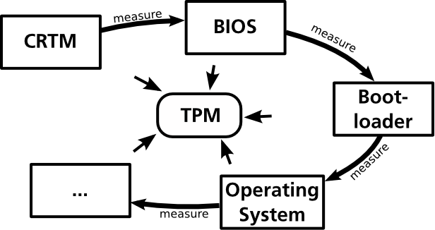
The result of this process is a chain of measurements, where one can trust that each component was measured before it was executed. This fundamental concept is referred to as Chain of Trust.
Roots of Trust
The description of the Chain of Trust made clear that Trusted Platforms need components that act as a Root of Trust (e.g. CRTM) that must work properly. TCG defines three kinds of Roots of Trust:
- Root of Trust for Storage (RTS): Refers to the component that is responsible for securely storing and managing of sensitive data (integrity measurements, keys). The RTS is implemented by the TPM.
- Root of Trust for Reporting (RTR): Refers to the component that is responsible for creating verifiable integrity reports. The RTR is also implemented by the TPM.
- Root of Trust for Measurement (RTM): Refers to the component that is responsible for taking the initial measurements at system boot. The RTM consists of two components: 1) the CRTM as described above and 2) the CPU that executed the instructions of the CRTM.
The Roots of Trust must work properly. Compromised Roots of Trust can not be securely detected.
Introduction to Trusted Network Connect
Trusted Network Connect (TNC) refers to an open, non proprietary framework for enhancing the security of modern networks. The basic concept is called Network Access Control (NAC). NAC is all about securing the connection of endpoints to a network. Besides TNC, there are many proprietary NAC approaches (e.g. MS NAP, Cisco NAC). In addition to being open, TNC distinguishes itself by leveraging the capabilities of Trusted Platforms as described in the previous sections.
Basically, TNC allows you to decide whether an endpoint gets access to you network or not based on the endpoints current integrity state. That is, the administrator of the network can specify a policy that every endpoint has to fulfill before network access is granted (the integrity is checked against the policy). E.g., an enterprise could enforce that any endpoint that wishes to connect to the corporate network must have an anti virus software running whose virus signature is up-to-date. User authentication can be done in addition to this integrity check of an endpoint. If this check fails, the endpoint is considered to be in an unhealthy state and one of the following access restrictions can be enforced:
- The access to the network can simply be denied.
- The endpoint can be isolated to a specific section of the network. From there, services should be available that the endpoint can use to remediate itself. Afterwards, another integrity check which should now be successful can be performed. This process is called Remediation.
The access decision is enforced at the network’s edge, e.g. by a switch or by a VPN. TNC aims to leverage existing technologies like VPN or 802.1X. Here is a good introduction to the basic concepts of NAC.
TNC Architecture
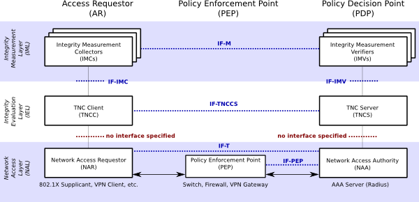
The TNC architecture consists of entities, layers, components and interfaces. A slightly simplified version of the architecture is depicted in the following figure (original version). The TNC architecture depicted below consists of three entities (the columns): Access Requestor (AR), Policy Enforcement Point (PEP) and Policy Decision Point (PDP). Each entity is made up by a set of components (the boxes). Those components are grouped into three layers (the horizontal shaded rectangles). Components communicate via standardized interfaces (blue dotted lines). The red dotted lines indicate interfaces that are not specified by the TCG (i.e., the communication is implementation specific).
Entities
There are three logical entities defined in the TNC architecture.
- The AR on the left is the entity that tries to get access to a protected network (e.g. a laptop).
- The PDP on the right is part of the protected network. It is responsible for making the decision regarding the network access request of the AR based upon policies defined by the network administrator.
- The PEP in the middle is responsible for enforcing the PDP’s decisions regarding network access request. E.g., considering a IEEE 802 LAN, a switch supporting IEEE 802.1X could act as PEP.
Layers
Three layers group similar components of the TNC architecture.
- The bottom one is called Network Access Layer. Components located in this layer are responsible for technically implementing and securing the basic network access. Multiple techniques can be user in this layer (e.g. IEEE 802.1X, VPN). Each entity has one component in this layer.
- The layer in the middle is called Integrity Evaluation Layer. Components of this layer are responsible for evaluating the integrity state of the AR based on given policies. They use data from components of the top layer (IML) as input for this evaluation process.
- The top layer is called Integrity Measurement Layer. There is an arbitrary number of components at this layer, which are responsible for retrieving and evaluating various integrity related aspects of an AR. The overall access decision (done by the components of the middle IEL) is based upon these single measurements.
Components
IML Components
The IML consist of an arbitrary number of components, normally pairs of components. Each pair consists of an IMC (on the AR) and a corresponding IMV (on the PDP). Each of those IMC/IMV pairs is responsible for measuring and evaluating certain, integrity related aspects of the corresponding AR. The IMC performs the measurement on the AR. By using the components of the two lower layers, these measurement messages are communicated to the corresponding IMV. The IMV evaluates the received measurements based upon defined policies. In the end, it knows to what extent the AR conforms to the given policy regarding the measured integrity aspects. This result is communicated as a recommendation to the TNCS in the IEL, stating to what extent network access shall be granted.
IEL Components
There are two components located in the IEL: the TNC Client (TNCC) on the AR and the TNC Server (TNCS) on the PDP. Their primary task is to enable the communication between IMCs and IMVs by gathering and forwarding/receiving their messages to/from the components of the NAL. Furthermore, the TNCS is responsible for making an overall access decision based on the recommendations provided by the IMVs. The overall access decision is forwarded to the NAA component (NAL).
NAL Components
There are three components located in the NAL. Within the AR, the Network Access Requestor (NAR) component realizes the technical network access (e.g. a IEEE 802.1X supplicant). On the PDP, this task is performed by the Network Access Authority component (NAA). Furthermore, the NAA is the component that decides whether an AR is granted access, based upon the access decision made by the TNCS.
Interfaces
The components normally communicate via interfaces that are standardized by the TCG. For a detailed description of each interface, please refer to the corresponding specification. However, two aspects should be noted.
- Although the IF-M interface between IMCs/IMVs is mentioned in the architecture diagram, there is currently no specification available for it. The reason is that normally, the messages send between one IMC and one IMV (which is normally developed by the same vendor) can be implementation specific and opaque to the rest of the TNC framework, without violating interoperability. However, for the future, TCG expects to standardize certain, widely useful IF-M interfaces.
- There are no interfaces defined for the communication between TNCC and NAR on the AR, respectively between TNCS and NAA on the PDP.
One special aspect of TNC is its support for the capabilities of a Trusted Platform. This enables to prevent a certain type of attack, referred to as Lying Endpoint Attacks. As described above, there are several components located on the AR. Those components are responsible for measuring the integrity of the AR. If those components are compromised, an AR is able to lie about its real integrity state. Thus, access to a protected network could be allowed, even though the requesting AR does not comply with the given policy on the PDP.
To prevent this kind of attacks, the integrity of the TNC components on the AR have to be measured and evaluated within the TNC handshake. That is, a Chain of Trust must be established, starting from system boot and including the TNC components on the AR. Therefore, TCG has specified an interface for Platform Trust Services (IF-PTS) that enables the use of the necessary Trusted Platform capabilities within a TNC handshake. Thus, lying endpoints can still be created. But thanks to the Trusted Platform capabilities, they can be securely detected.
The Trusted Computing approach specified by the TCG promises to significantly increase the security level of modern computing systems. However, the proposed concepts and the TCG itself had to face an immense amount of criticism in the past. One of the most prominent critics is Ross Anderson. Since the new foundation of the TCG (formerly known as Trusted Computing Platform Alliance TCPA), one aims to polish up the reputation. Higher transparency of the specification process and the free availability of published specifications shall regain the trust of others.
Privacy Concerns
Critics claim that a TPM threatens the privacy of the user. The thesis is that any transaction or communication that is secured by using the TPM can be correlated just because a TPM was used (specifically keys that are bound to a certain TPM were use). This is not true. The current version 1.2 of the TPM specification provides two mechanisms that ensure the privacy of a user (AIK-CA and DAA). Thus, a TPM rather provides mechanisms to increase the privacy of the users.
Loss of Control
Critics claim that a user might lose control of its own computing platform due to Trusted Computing technology. This is true, to some extent. Reasons are the functions of Attestation and Sealing. That is, in principle, a service provider could dictate a user which software he or she has to use to be able to consume a provided service. Imagine a provider of MP3 files. This provider could seal the MP3 files to a integrity state of a system in such a way, that the file can only be used by a certain player.
It is important to note that this issue does not refer to Trusted Computing or the TCG itself. Instead of that, the described scenario is a kind of abuse. TCG has reacted on this topic and points out that the described scenario is not a desired use of the Trusted Computing technology. There is a best practises document available at the TCG.
21 Nov 2008
 This picture shows all components that are used on the serverside of tnc@fhh.