tnc@fhh 0.6.0 released
The final version 0.6.0 of tnc@fhh is now available for download.
Some changes were made to this release compared to the RC1 version:
- Fixed some bugs (00000019, 00000023, 00000024) discovered in 0.6.0 RC1 (see Mantis Bugtracking for more details)
- Added imunit-dev. This is a new project targeted for IMC/V pair developers. It contains the imunit framework plus additional documentation that describes the development of IMC/V pairs based upon imunit. An new example IMC/V pair is also included.
Note: We decided to change the naming of TNC@FHH to tnc@fhh. Currently, the two names can be used interchangeably.
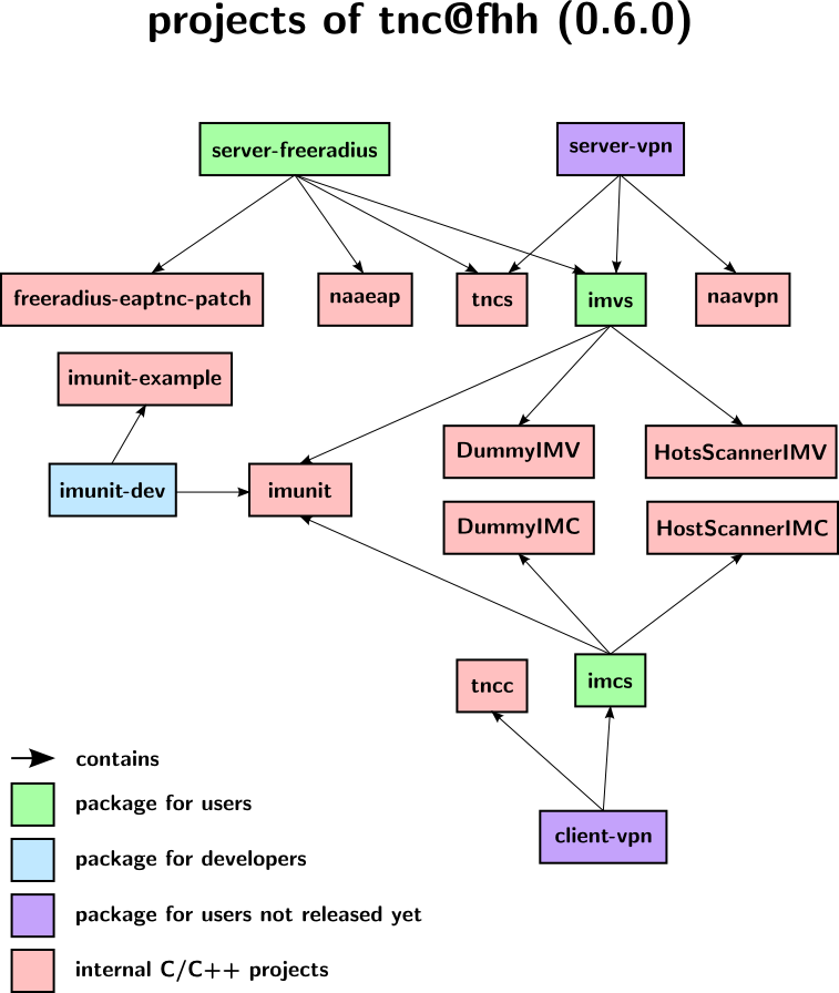
The package structure of this release is as follows:
You can find the tarballs in the download section. The 0.6.0 RC1 has been moved to the archive.
17 Sep 2009
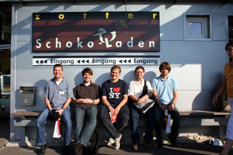
ETISS 2009 in Graz
The Trust@FHH team participated in the ETISS 2009.
The European Trusted Infrastructure Summer School 2009 was held in Graz, Austria. The Trust@FHH team participated in this year’s summer school. We were asked to give a lecture and to run a lab about Trusted Network Connect.
Thanks to IAIK for hosting such a great event.
09 Sep 2009
tnc@fhh 0.6.0 RC 1 released
Release Candidate 1 of tnc@fhh 0.6.0 is available for download.
This new release introduces a set of new features:
- improved framework for developing IMC/IMV pairs
- cmake based build process
- new package structure (see below)
- first steps to support IF-TNCCS SoH and IF-TNCCS 2.0
- decoupling of TNCS and NAA logic (now provided as two separate shared objects)
- using log4cxx as logging framework
From now on, tnc@fhh software will be provided in a more convenient package structure.
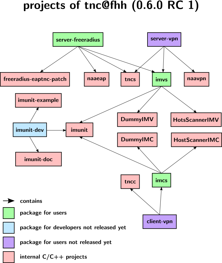
The 0.6.0 RC 1 release consists of three packages (the green boxes)
- imcs: contains all tnc@fhh IMCs and the necessary library imunit
- imvs: contains all tnc@fhh IMVs and the necessary library imunit
- server-freeradius: contains all tnc@fhh components necessary for setting up a PDP based upon FreeRADIUS
The tarballs are available in the download section.
21 Aug 2009
Trust@FHH at LinuxTag 2009
The Trust@FHH Team Member Joerg Vieweg gave a talk about Trusted Network Access Control based on Open Source Software - Experiences from Adoption at the LinuxTag 2009 in Berlin.
The talk was aimed to explain how open source software based upon Trusted Computings Trusted Network Connect can help to increase the security of today’s IT systems, especially in the area of modern networks.
In the first part, we gave a general introduction into the concepts of Trusted Network Connect as proposed by the Trusted Computing Group.
The second part presented projects of the Trust@FHH research group that deal with open source software and Trusted Computing as proposed by the TCG, especially the Trusted Network Connect approach.
Three active projects that were presented in the talk:
- IF-MAP@FHH, an implementation of the IF-MAP specification
- TNC@FHH, an implementation of the TNC architecture
- tNAC, a project that aims to develop a TNC compatible NAC solution that uses the capabilities of Trusted Computing platforms.
All software that is developed within these projects is completely open source.
The talk finished with an outlook of current challenges and unsolved problems in the area of Trusted Computing and Trusted Network Connect.
27 Jul 2009
Redesigning the Redesign - TNC@FHH IML Components Version 0.6.0 Alpha released
TNC@FHH’s components of the Integrity Measurement Layer (IML) are now available for download in an updated version.
We have redesigned all TNC@FHH components that are located in the Integrity Measurement Layer (IML). The downloadable package includes:
- IMUnit: a framework for developing IMC/IMV pairs
- DummyIMC/IMV: a simple IMC/IMV pair that just sends some messages around before a recommendation is provided
- HostScannerIMC/IMV: an IMC/IMV pair that scans and evaluates the port status of an endpoint
Major changes to version 0.5.0 are:
- TNCUtil was removed
- Log4cxx is now used for logging purposes
- IMUnit has now a more object oriented approach
- Bug 0000015 was fixed
These IML components are fully compatible with NAA-TNCS version 0.5.0.
22 Jun 2009
tnc@fhh 0.5.0 released
The new version 0.5.0 of tnc@fhh is available for download.
This version includes major changes regarding the build process. We switched to cmake as our new build environment. The HowTos in the Wiki will be updated shortly. Furthermore, we are now providing all tnc@fhh components in one tarball.
The build process now looks basically as follows:
extract tarball
switch to <new directory>/build
cmake ../
make
make install
The FreeRADIUS EAP-TNC patch is not affected by the cmake-switch and therefore not included in this tarball.
25 May 2009
tnc@fhh participates in TCG Plugfest 2009
tnc@fhh was successfully tested with other open-source projects at the TCG Plugfest 2009.
The plugfest was hosted by the University of New Hampshire InterOperability Lab. We were able to participate remotely thanks to the great virtual environment that was provided by the organizers of the Plugfest. Several TNC interfaces were sucessfully tested, including
- IF-TNCCS
- IF-IMC
- IF-IMV
- IF-PEP
See the news entry and the short overview by Lisa Lorenzin from Juniper for more information.
08 May 2009
Trust@FHH registered an IANA Private Enterprise Number
The University of Applied Sciences and Arts Hanover has registered an IANA Private Enterprise Number.
The PEN is 32939 decimal. The Trust@FHH research group will use this PEN as Vendor ID within TNC.
Updated versions of the IMC/IMV pairs are available in the download section.
13 Mar 2009